
open source motion tracking
Early in my PhD I developed an open-source motion tracking system for mice - now for sale at LABmaker 😄! With the KineMouse wheel neuroscientists can reconstruct 3D pose while recording neural activity. The hackaday protocol describes how to build the system. This supplement contains additional info for motion tracking aficionados. Please be nice to your mice ❤️🐭❤️.
cameras
playstation eye
Many labs use PlayStation Eye cameras, which are super cheap and can achieve high frame rates (60-120 Hz depending on frame size). You can also get tons of lenses from this site to customize the view. Keep in mind both the lens and the lens holder affect the view. Thicker lens holders push the lens further from the camera sensor, which magnifies the image.
FLIR / PointGrey
I use FLIR cameras. They have many options that are not too expensive. Depending on the model they can achieve higher frame rates that Playstation Eyes. Some benefits to getting a real machine camera:
- more customizability, e.g. setting pixel format, image cropping, frame rate, exposure time, etc…
- camera sends metadata (e.g. frame time, frame count) along with frames, which can be critical for synchronizing different data streams
- many have digital inputs and outputs, meaning you can trigger frame acquisition from an external device (e.g. an Arduino), or record the times at which frames were captured.
I use two PointGrey cameras in my rig: a Grasshopper for the main camera (GS3-U3-23S6M-C), and a Chameleon for a zoomed in view of just the whiskers (CM3-U3-13Y3M).
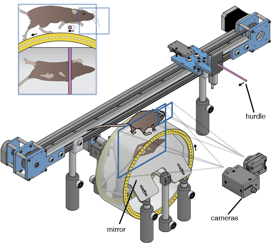
My setup is shown below. Ignore the linear track and all the ‘hurdle’ stuff:
perspective distortion
In an ideal world, the camera would be capturing an orthographic projection of the stuff it is viewing. However, light bends as it enters the lens, leading to perspective distortion. This can reduce the accuracy of the 3D tracking, unless we want to calibrate our cameras using a software toolkit such as anipose.
Fortunately, there is an easy work around. Perspective distortion decreases as the camera is moved further away. I therefore keep my camera ~5 feet from the wheel. Make sure you get a camera lens that is appropriate for this distance though (see below).
image resolution
Most cameras have more pixels crammed into their sensors than you actually need. For example, my camera has 1920×1200 resolution. If I use all of these pixels my files will be huge, my frame rates will be slow, and I will have ~5x the necessary spatial resolution in my images.
Solution: buy a lens that captures more of the field of view than you actually need (e.g. if you are imaging at 10cm x 10cm area, get a lens that captures 30cm x 30cm). Then (with FLIR cameras) you can select an ROI than captures just the wheel and the mouse. By selecting an ROI you will drastically decrease file sizes while increasing the maximum possible frame rate. The spatial resolution (i.e. pixels / mm) will be smaller.
lenses
The lens you use is super important. The focal length of the lens should be appropriate for the size of the wheel and the distance of the camera to the wheel. There are several online calculators that allow you figure out the right focal length given these characteristics of your rig. Alternatively, you can talk to the customer support reps here. If you tell them how far away your camera will be, and the size of the viewing field, they will recommend appropriate lenses.
frame rate
I find 250 Hz to be sufficient to capture even very fast movements. I suspect you could get away with 120-ish for most behaviors. According to Nyquist should should sample twice as fast as the fastest aspect of the behavior.
measuring wheel movements
rotary encoder
A rotary encoder can be attached to the shaft of the wheel to monitor it’s movement. Generally, there are analog encoders that spit out (say) 0-5V depending on the angular position of the shaft (the signal will be discontinuous when it wraps around from 5 back to 0 volts). These should be fine for most purposes, but digital encoders offer greater accuracy at the expense of having to deal with decoding the signal.
I use this optical digital encoder. It uses what’s called a quadrature code to encode the position of the shaft. Basically, there are two digital outputs; both are square waves that are 90 degrees offset from one another. The square waves advance as the wheel is turned. Every time the state of the outputs changes, you know the wheel have moved (see rotary encoder software below for details).
rotary encoder mount
I’ve designed a simple mount for this specific rotary encoder:
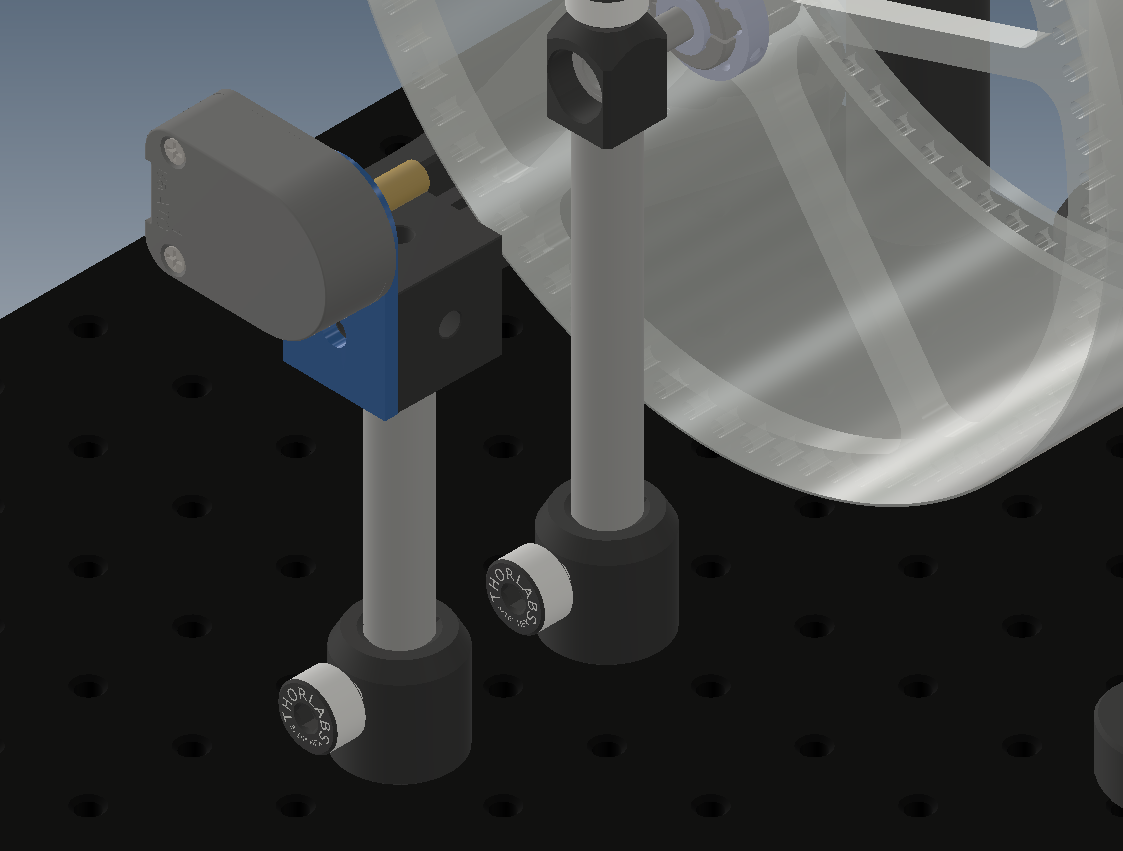
In addition to the parts listed in the hackaday protocol, all you need is:
- An additional Thorlabs TR4 post
- An additional Thorlabs PH1 post holder
- A Thorlabs RM1F construction cube
- This custom piece I designed (the units are inches in the .dxf file). Laser cut this piece in 1/8” acrylic and assemble as shown in the picture above.
- A 1/4” shaft coupling (not shown in the picture above) to attach the shaft of the wheel to the rotary encoder. Something like this (a bit fancy) or this (less fancy, will still work).
rotary encoder software
Okay, I was a little vague about how the digital rotary encoder output works above. See this for an excellent explanation (with code). The basic idea is that when the state of the pins change you know the wheel has moved. You can figure out exactly how far by comparing the counts per revolution of your encoder (the numbers of periods of the square wave in one revolution) to the radius of the wheel. However, you don’t know if it moved forward or backwards. You can solve the problem as follows:
- There are two digital outputs, each of which is a square wave that is 90 degrees out of phase with the other one.
- Therefore, at any time the state across both outputs is either
00,10,01, or11 - When the state changes (which can be detected with a software interrupt), you end up with four bits, corresponding to the two bits of the previous state and the two bits of the subsequent state, e.g.
10$\rightarrow$11, or00$\rightarrow$10, etc… Each of the 16 possible collections of four bits is associated with a forward movement, a backward movement, or no movement at all.
You can use a super efficient lookup table in an Arduino to integrate these changes and track the position of the wheel. See details here. However, if you want to record these values for later use you’ll have to get the information from your Arduino to a computer, which could be done via the Serial port. Alternatively, you can record the digital outputs and decode them offline, e.g. in MATLAB or Python.
data acquisition
I highly recommend the open-source, neuroscientist-created Bonsai software for image acquisition. It allows you to capture videos as well as other data in parallel, e.g. neural recordings from an open ephys acquisition board and serial input from an Arduino.
online video compression
The creators or DeepLabCut and I discovered that you can compress the heck out of your videos without sacrificing tracking accuracy. This can save enormously on disk space. ffmpeg is a ubiquitous, command line video editing software that can be used for video compression. Bonsai can compress videos with ffmpeg during acquisition 😱. Please see the Bonsai user group for more details. This is a good thread to start with, although I think there are better ways of implementing this idea using newer Bonsai functionality.
3D tracking
I recommend using DeepLabCut or DeepPoseKit for tracking. For the main camera I train a single network on both of the views. I also have a camera focused on the whiskers that I use to tracked jaw, tongue, and whisker movements:
![]()
I rely on the following heuristics to stitch things together in 3D:
- The x (anterior-posterior) position of the same feature (e.g. left forepaw) should be shared in both views because they are orthogonal.
- The bottom view is more reliable due to lack of occlusion. I therefore track x and y (medio-lateral) in the bottom view, and only use top view for z (dorsal-ventral).
If you want a more hardcore 3D reconstruction method I recommend checking out anipose. This will require calibrating the cameras.
super fast wheel 🔥🔥🔥
My personal KineMouse wheel is different than the one published online in two respects:
- The spokes are super thin and waterjet cut out of aluminum. This makes the whole thing lighter, but the waterjet cutting is expensive and not widely available.
- I also had track marks waterjet cut directly into the polycarbonate floor. This means I don’t have to cover the floor with anything for traction, and it makes the whole thing lighter. This was also expensive. I don’t recommend going this route unless you need super fast locomotion.